 702461526
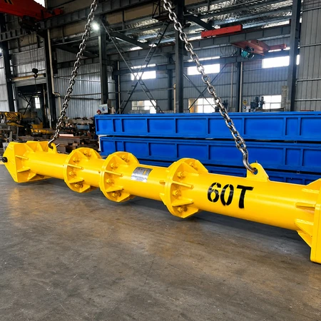

Lift sling rigging company produce Spreader beam,4-point Spreader Frame Beam,adjustable spreader beam,Stainless steel spreader beam.
Spreader Beam
Fixed, Adjustable, Modular & Telescopic Spreader Beams — 100 kg to 180 Tonnes, Spans to 25 m
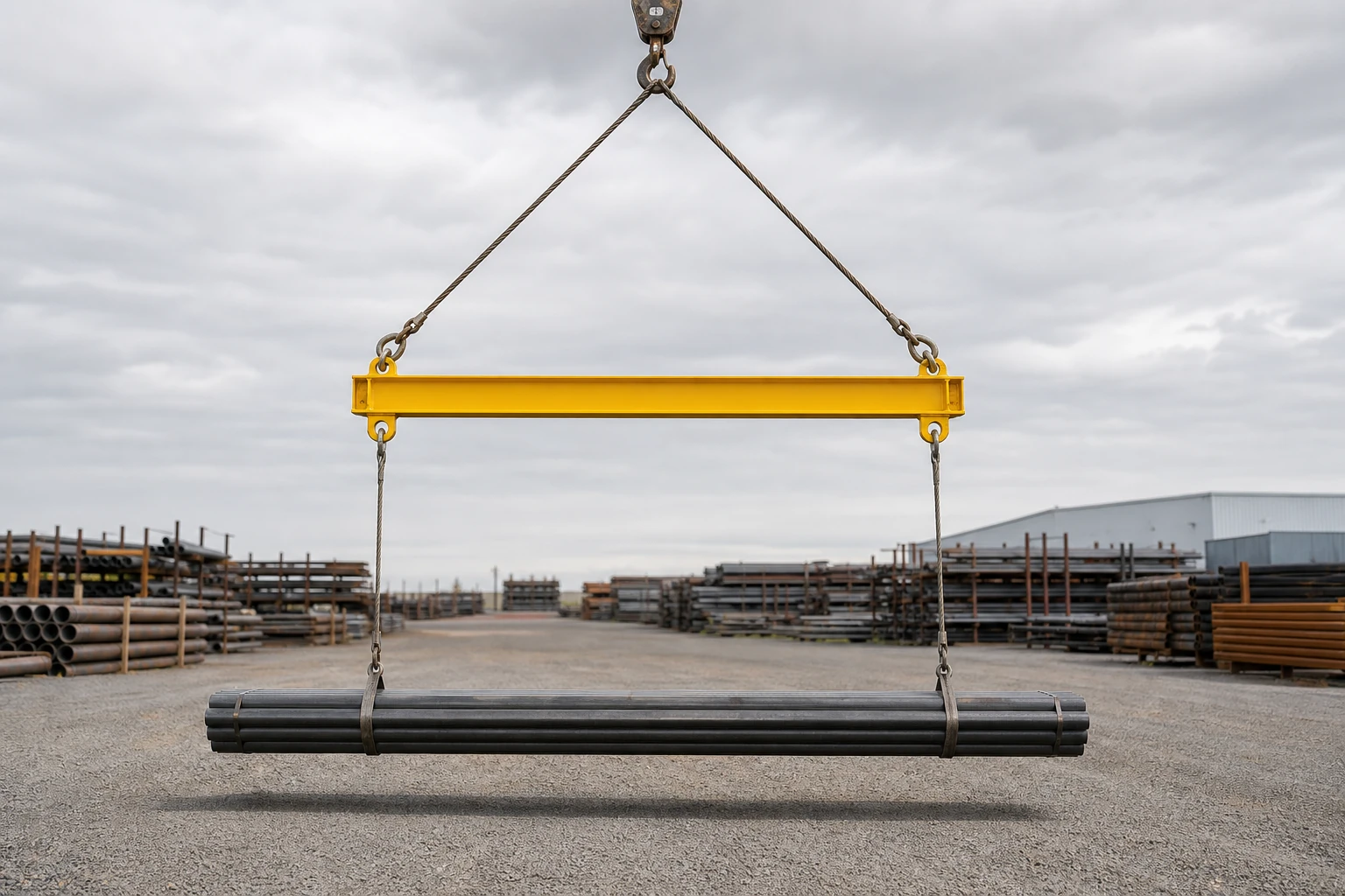
A spreader beam is a horizontal member hung from the crane hook on two suspension slings that form a V, with the load suspended below it on vertical slings. That arrangement changes what the beam has to do. The upper slings are inclined, and their horizontal components put the beam into pure compression — it works as a strut, not as a beam in bending. For the same capacity and span that usually makes it the lighter, shallower and more stable solution. We manufacture fixed, adjustable, modular and telescopic spreader beams and lifting spreader beams from 100 kg to 180 tonnes, in spans to 25 m, proof load tested before dispatch.
- The load is never squeezed — lower slings hang vertically, so the pick points do not pull inward on the load
- Lighter for the same job — a beam in compression needs less steel than one in bending at equal span
- More stable under load — the upper V slings resist sway and rotation
- Adjustable, modular or telescopic — one beam covers a range of load lengths and spans
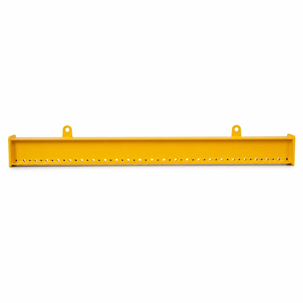

Key Features of Our Spreader Beam
Works in Compression
The upper slings are inclined, so their horizontal components load the beam axially. A member in pure compression needs far less steel than one in bending, which is why a spreader beam is normally the lighter choice at the same capacity and span.
Vertical Lower Slings
Below the beam the slings hang vertically, so the pick points sit directly above the attachment points and put no inward squeeze on the load — important for pipes, finished surfaces and long fabrications.
Better Load Stability
The upper V slings also act as a stabiliser: they resist sway, yaw and rotation far better than a single-point pick, which makes long loads easier to land accurately.
Adjustable and Modular
Multiple lower attachment holes, a sliding trolley, a telescopic joint, or a bolt-together modular beam that ships in sections and is rebuilt at the span the lift needs.
Spans Where Beams Get Heavy
Truss and H-section construction carries the compression efficiently over long spans, so a spreader beam stays a practical solution where a bending-type beam would become impractically heavy.
Tested and Documented
Proof load tested to 125 % of rated capacity before dispatch, with the rated capacity, tare weight, serial number and year of manufacture marked on the beam and a test certificate supplied.
Spreader Beam vs Lifting Beam
The two names are often used interchangeably, but the rigging is different and so is the way the steel is loaded. It is worth knowing which one your lift actually needs, because the choice changes the headroom, the beam’s weight and how it behaves over the load.
| Spreader beam | Lifting beam | |
|---|---|---|
| Upper rigging | Two or more suspension slings forming a V from the hook to the beam | None — a single pick point on top of the beam, often above the centre of gravity |
| Lower slings | Vertical | Vertical |
| Beam is loaded in | Compression — it acts as a strut | Bending — it acts as a beam |
| Section for equal capacity and span | Lighter and shallower | Heavier and deeper |
| Headroom | Needs more — the beam hangs below the hook by the height of the V | Needs less — the beam sits close under the hook |
| Stability | Higher — the V resists sway and rotation | Lower — a single pick can swing and rotate |
| Usually chosen for | Long spans, long loads, high capacity, stability | Low-headroom lifts, tight spaces, specific fixed pick points |
How a Spreader Beam Works
There are two separate sling systems on a spreader beam, and they do different jobs. The upper rigging runs from the crane hook down to the suspension lugs on top of the beam — usually two slings, so the beam hangs in a V. The lower rigging runs from the load attachment points on the underside of the beam straight down to the load. The upper slings are inclined; the lower slings are vertical.
It is the inclination of the upper slings that defines the spreader beam. Each upper sling carries a share of the load, and because it is not vertical, part of that tension pulls sideways along the beam. Both slings pull inward, so the beam is squeezed — loaded in pure compression — and the amount depends entirely on how steep the upper slings are.
Setting the top slings
Steeper top slings mean less compression in the beam but a taller rig; shallower slings mean a lower rig but a much heavier compressive load. The table shows how quickly that changes.
| Top sling angle α (from horizontal) | Compression in the beam | Tension per upper sling |
|---|---|---|
| 90° (vertical) | 0 — the beam is no longer a spreader beam | 0.50 × load |
| 60° | 0.58 × load | 0.58 × load |
| 45° (common working angle) | 1.00 × load | 0.71 × load |
| 30° | 1.73 × load | 1.00 × load |
| 20° | 2.75 × load | 1.46 × load |
In practice the top slings are usually set between about 45° and 60° from the horizontal. Going shallower than 45° starts to drive the compression up sharply and also forces very long slings, so it is rarely the economical answer. Tell us the headroom and the load length and we will size the suspension points so the rig works at a sensible angle.
Types of Spreader Beam
| Fixed spreader beam | Suspension and load points welded in fixed positions. The lightest and simplest option when the load size is constant. |
|---|---|
| Adjustable (multi-position) spreader beam | A row of lower attachment holes, or a sliding bracket, so the load pick points can be moved along the beam to suit different load lengths or to trim an off-centre load. |
| Telescopic spreader beam | An inner section slides inside the outer beam and locks with pins, so the span can be adjusted on site. Ideal for a lifting yard handling mixed load sizes. |
| Modular spreader beam | Bolt-together sections that ship in manageable pieces and are assembled at the span the lift requires. One set covers many spans, and transport cost stays low. |
| Truss / lattice spreader beam | Lattice construction for long spans and high capacity, where compression is carried most efficiently and a solid section would become too heavy. |
| Container spreader beam | A frame arrangement with dedicated corner fittings for handling containers and containerised cargo in ports and yards. |
Technical Specifications
| Product name | Spreader beam / spreader bar / lifting spreader beam / modular spreader beam / telescopic spreader beam |
|---|---|
| Rated capacity (WLL) | 100 kg to 180 t standard range; larger custom designs quoted on request |
| Span / overall length | 0.5 m to 25 m depending on capacity and section (custom) |
| Beam section | Welded box section · welded H-section · lattice truss for long spans and high capacities |
| Material | Q235B / Q345B (S235JR / S355JR) structural steel; high-strength steel for large-tonnage designs |
| Welding | Full-penetration welds by qualified welders; weld inspection records available on request |
| Upper suspension points | Two welded suspension lugs (standard) · four for wide or long beams · stainless or plated pins |
| Lower attachment points | Pin holes · shackle lugs · swivel hooks · sliding brackets · 2, 4 or more points, fixed or adjustable |
| Top sling angle | Normally set between 45° and 60° from the horizontal — confirmed against your headroom and load |
| Design factor | Applied against the rated capacity per the applicable standard and service class — typically 3:1 to 5:1; confirmed per project |
| Proof load test | 125 % of rated capacity before dispatch, with a load test certificate |
| Surface treatment | Shot blast to Sa 2.5 + epoxy primer + polyurethane topcoat (safety yellow) · optional hot-dip galvanising |
| Marking | Rated capacity (WLL), tare weight, serial number and year of manufacture marked on the beam |
| Documentation | General arrangement drawing, material certificate, weld record and proof load test certificate |
| Reference standards | Designed and manufactured with reference to ASME B30.20 / ASME BTH-1 and EN 13155 practice for below-the-hook lifting devices — confirm the standard and design factor that apply in your market |
| Options | Adjustable or telescopic span · modular bolt-together sections · matched upper and lower slings · shackles · swivel hooks · tag line points · storage stand · custom colour |
| Packing | Steel frame or pallet, seaworthy packing for export; modular beams ship in knockdown sections |
| MOQ & OEM | Single units and fully custom designs welcome; OEM with your own markings and documentation |
Capacity and Span Range
Span drives the design. Because the beam carries axial compression, doubling the span raises the compression load and the buckling length together — so the section grows quickly, though less quickly than it would for a beam in bending. The table shows the practical span range for each capacity band. Tell us the capacity, the span and the number of lower attachment points and we will confirm the section and the beam’s own weight.
| Rated capacity (WLL) | Typical overall length / span | Lower attachment points | Typical beam type |
|---|---|---|---|
| 0.5 t | 1.0 – 2.5 m | 2 | Box section |
| 1 t | 1.0 – 3.0 m | 2 | Box section |
| 2 t | 1.5 – 4.0 m | 2 | Box section |
| 3 t | 2.0 – 5.0 m | 2 | Box section |
| 5 t | 2.5 – 6.0 m | 2 | Box section |
| 10 t | 3.0 – 8.0 m | 2 or 4 | Box / welded H |
| 16 t | 4.0 – 10.0 m | 2 or 4 | Welded H |
| 20 t | 5.0 – 12.0 m | 2 or 4 | Welded H |
| 32 t | 6.0 – 14.0 m | 4 | Welded H / truss |
| 50 t | 8.0 – 16.0 m | 4 | Welded H / truss |
| 80 t | 10.0 – 18.0 m | 4 | Truss |
| 100 t | 10.0 – 20.0 m | 4 | Truss |
| 180 t | 12.0 – 25.0 m (custom) | 4 or more | Custom truss |
Design, Testing and Documentation
- Designed against your load case — rated capacity, span, the top sling angle, the number and position of lower attachment points and the headroom available are all design inputs, not afterthoughts.
- Compression and buckling checked — because the beam works as a strut, the design checks axial capacity, buckling over the unbraced length and the end connection details, not just bending stress.
- Full-penetration welding — lug plates and end fittings are welded by qualified welders, with weld inspection records available on request.
- Proof load tested — every beam is proof load tested to 125 % of its rated capacity before dispatch, and the test certificate is issued with the beam.
- Clearly marked — rated capacity, tare weight, serial number and year of manufacture are marked on the beam.
Applications
- Pipes, tube bundles and bar bundles where the load must stay level and unmarked
- Fabricated tower sections, cans and pressure vessel shells
- Long steel sections, rails, beams and piling
- Precast concrete panels, beams and pile sections
- Steel plate and sheet packs, and coated or painted surfaces
- Timber packs, board bundles and palletised loads
- Container and containerised cargo handling in ports and yards
- Wind turbine components and other long, heavy fabricated parts

Adjustable, Modular and Telescopic Options
Very few lifts are identical, so most spreader beams we build are adjustable in some way. These are the three approaches, and they solve different problems:
- Adjustable lower attachment points — a row of pin holes or a sliding bracket along the beam. Use this to match different load lengths and to trim the pick points until an off-centre load hangs level. The span stays fixed.
- Telescopic beam — the span itself changes. An inner section slides inside the outer and locks with pins, so one beam covers a range of load lengths on site.
- Modular beam — the beam is made from bolt-together sections. It ships in manageable pieces, is assembled at the span the lift needs, and can be reconfigured as requirements change. The usual choice when spans are long or when transport and storage space is limited.

Customisation and OEM Service
- Capacity and span — 100 kg to 180 t, spans to 25 m, or a one-off design outside that range
- Suspension and attachment points — 2, 4, 6 or more; fixed, multi-position, sliding or telescopic
- Complete rigging sets — matched upper suspension slings, lower slings, shackles and hooks supplied with the beam
- Section and finish — box, H-section or truss; safety yellow, your own colour, or hot-dip galvanised for outdoor and marine use
- Marking and documentation — your own tag format, part numbers, drawings and certificates
Quality Control
Each beam is checked on dimensions, plate thickness, weld quality, lug and hole geometry and surface finish before testing, then proof load tested and re-inspected. We have manufactured lifting equipment for industrial, construction, port and power customers for close to three decades — including 100-tonne class lifting belts and large-tonnage lifting devices — and we keep the process visible: on request we supply the material certificate, the weld record, the general arrangement drawing and the proof load test certificate for your beam.
Frequently Asked Questions
What is the difference between a spreader beam and a lifting beam?
A spreader beam is hung on two suspension slings that form a V, so the inclined slings put the beam into pure compression and the load hangs from vertical lower slings. A lifting beam has a single pick point on top of the beam, so the beam works in bending instead. A spreader beam is normally lighter for the same capacity and span and is more stable, but it needs more headroom; a lifting beam is the better choice where headroom is limited.
Why does a spreader beam need a sling above it?
Because that is what makes it a spreader beam. The inclined upper slings create the horizontal component that loads the beam in compression, and they also stabilise the lift. With vertical upper slings the beam would carry no compression at all — it would be a lifting beam in bending, which is a different and heavier solution.
What angle should the top slings be set at?
Between about 45° and 60° from the horizontal in most cases. At 45° the compression in the beam equals the load; at 30° it rises to about 1.73 times the load, and the slings also have to be very long. Steeper than 60° means a taller rig but less compression in the beam.
How do I choose the capacity and span?
Start from the load weight, then confirm the span is the actual distance between the lower attachment points — not the length you happen to have available. The beam’s own dead weight and the rigging weight both come off the crane’s capacity, so they are part of the calculation, not an afterthought.
Can one spreader beam cover several load sizes?
Yes. Adjustable lower attachment points let you reposition the pick points along a fixed beam; a telescopic beam lets you change the span; a modular bolt-together beam lets you rebuild the beam at whatever span you need. Tell us the range of load lengths you handle and we will advise which option is the best balance of flexibility and weight.
Is a spreader beam tested before delivery?
Yes. Every beam is proof load tested to 125 % of its rated capacity before dispatch and is issued with a load test certificate. The rated capacity, tare weight, serial number and year of manufacture are marked on the beam itself, and the material certificate, weld record and general arrangement drawing are available on request.
Request a Quote for a Spreader Beam
Send us the load weight, the span, the number of attachment points, the crane hook and the headroom available. Our team will come back with a proposed section, dead weight, rigging and a factory-direct price.